CONCENTRIC BUTTERFLY VALVES
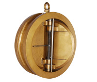 |
Advance Butterfly Valve are designed & manufactured to have optimum mix of structural stability, flow efficiency & effective seating coupled with advantage of light weight, compact design and ease of operation. Only a quarter turn is needed to fully open or close the valves. |
| The salient features include :- | |
|
|
Design Features | Construction Features | Facilities (operators) | Application | Installation Dimensions
Design Features
The valves are designed and manufactured to have optimal mix of structural stability, flow efficiency and effective seating coupled with advantage of light weight, compact design and ease of operation.
The valves are provided with integrally moulded elastomer body liner for perfect seating and complete isolation of body material from fluid media. No gaskets are required as the body liner effects a perfect seal between the valve body and the mating pipe flanges.
The valves are designed using Finite Element Methods.
Advance Butterfly Valves conform to BS:5155, IS:13095 and also API 609. It also generally complies with AWWA C-504, International standard ISO 10631 and draft European standard pr EN 593.
Construction Features
Body is one piece design. Top Flange is designed to mount required Valve Operator.
Body Liner is integrally moulded and bonded to the body. It provides the seating to valve disc, primary seal to the stem and ‘gasket’ joint with mating pipe flanges. Integrally moulded liner resists any stretching or distortion of the liner which is a common problem of loosely fitted liner leading to frequent replacements.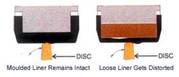
Valve Disc material covers wide range of applications. It is optimally designed to have an ideal combination of strength and flow efficiency.
Stem
For optimal combination of flow efficiency and structural stability, Valves upto 200mm (8″) have two piece stem. For sizes 250mm (10″) to 600mm (24″) N.B. stem is in single piece construction which ensures better distribution of weight of the disc. The stem drives the disc through taper pin(s) to eliminate any backlash between Stem & Disc. The material of construction for stem has been standardised as High Tensile Stainless steel (AISI 410).
Stem Seal Arrangement
Primary Sealing is provided by preloaded contact between flat seat surface and rounded polished disc hub area.
Secondary Sealing is provided by the interference fit b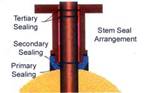 etween stem and stem hole in seat at all positions.
Even a tertiary sealing has been provided by fitting moulded O-ring between stem and bush supported by atmospheric sealing with O-rings. Thus Advance Butterfly Valves provide perfect sealing needing no other gland packing
End Connections
Wafer type flanges are as per BS 4504 PN 10 & 16, BS 1560 classes 125 & 150, ANSI B 16.5 Class 150, ANSI B 16.1 Class 125, BS 10 Table D, E & F and Indian Standard IS 6392 Table 10 to 20. Lug type valves are supplied to suit customers specifications.
Facilities
Technology Advantages
Rubber technology is fully developed in-house with facilities to mould, process all elastomers including mixing, vulcanizing and metal to elastomers bonding. The integral liner concept is a fail safe design.
Tests Offered
Extensive in-house testing facilities are available to fully ensure quality at all stages. These include :
- Elastomer Test for Tension, Compression set, Hardness, Specific Gravity, Adhesion & Abrasion Resistance.
- Dye Penetrant Test
- Tests of Actuators (both electric & pneumatic type)
- Hydrostatic Pressure Testing for shell & seat
- Pneumatic Testing for seat
- Valve operating torque test. Facilities for Pressure Drop test and Life cycle test exist for valid for upto 500 mm (20″) NB.
Apart from above, other NDT processes including MPI & Ultrasonic Test and tests for chemical & physical properties including special tests e.g. low temperature impact Test, Inter-granular Corrosion Test etc. are also offered to meet customers requirement through independent Approved Inspection and Test Laboratories.
Valve Testing:(Hydrostatic)
Each valve is hydrostatically tested for seat & shell tests as per applicable standards.
Additional tests as required can be carried out as per customer’s specification and requirement.
Application
The valves are available for all flluid service requirements with suitable body liner, disc material combinations for upto 210o deg.C in PN6, PN 10, PN 16, ANSI 125 & 150 rating.
- General Industry.
- Oil & gas production processing.
- Metallurgy.
- Water Supply & Management systems.
- Power plants.
- Sea water applications.
- Chemicals & Petrochemicals.
- Air & Gas Services.
Though R & D efforts, improvement & optimization of design is an ongoing process. The design/specifications provided here are subject to change accordingly.
 |
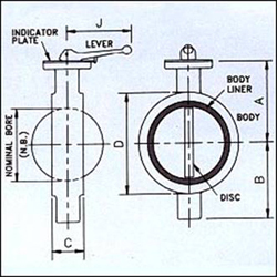 |
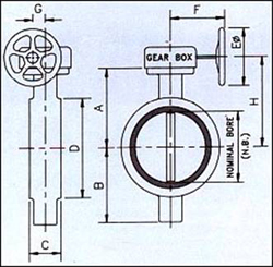
| VALVE SIZE (N.B.) | A | B | C | D | E | F | G | H | J | Approx. Gr. Wt. Kg. |
| 50 (2″) | 113 | 68 | 43 | 97 | – | – | – | – | 250 | 3.5 |
| 65 (21/2″) | 121 | 74 | 46 | 110 | – | – | – | – | 250 | 4.0 |
| 80 (3″) | 128 | 81 | 46 | 129 | – | – | – | – | 250 | 4.5 |
| 100 (4″) | 146 | 96 | 52 | 161 | – | – | – | – | 250 | 6.2 |
| 125 (5″) | 158 | 114 | 56 | 188 | – | – | – | – | 250 | 7.7 |
| 1500 (6″) | 174 | 132 | 56 | 212 | – | – | – | – | 250 | 9.0 |
| 200 (8″) | 198 | 165 | 60 | 269 | – | – | – | – | 250 | 14.0 |
| 250 (10″) | 245 | 215 | 68 | 320 | 300 | 175 | 61 | 283 | – | 30.0 |
| 300 (12″) | 275 | 240 | 78 | 370 | 300 | 175 | 61 | 313 | – | 44.0 |
| 350 (14″) | 305 | 265 | 92 | 436 | 300 | 175 | 61 | 343 | – | 50.0 |
| 400 (16″) | 335 | 295 | 102 | 487 | 450 | 265 | 117 | 408 | – | 72.0 |
| 450 (18″) | 386 | 325 | 114 | 539 | 450 | 265 | 117 | 459 | – | 95.0 |
| 500 (20″) | 416 | 360 | 127 | 592 | 450 | 265 | 117 | 489 | – | 120.0 |
| 600 (24″) | 506 | 435 | 154 | 695 | 450 | 265 | 117 | 579 | – | 210.0 |
| ( MODEL-21 ) | ||||||
| SIZE IN MM | SIZE IN INCHES | A | B | C | D | E |
| 50MM | 2 | 113 | 68 | 43 | 165 | 26 |
| 65MM | 2.5 | 121 | 74 | 46 | 185 | 46 |
| 80MM | 3 | 128 | 81 | 46 | 200 | 65 |
| 100MM | 4 | 146 | 96 | 52 | 229 | 86 |
| 125MM | 5 | 158 | 114 | 56 | 254 | 112 |
| 150MM | 6 | 174 | 132 | 56 | 285 | 139 |
| 200MM | 8 | 198 | 165 | 60 | 343 | 191 |
| 250MM | 10 | 244 | 215 | 68 | 406 | 241 |
| 300MM | 12 | 275 | 240 | 78 | 480 | 290 |
| 350MM | 14 | 371 | 265 | 78 | 533 | 324 |
| 400MM | 16 | 390 | 295 | 102 | 597 | 367 |
| 450MM | 18 | 425 | 325 | 114 | 635 | 413 |
| 500MM | 20 | 451 | 360 | 127 | 715 | 460 |
| 550MM | 22 | 481 | 408 | 154 | 762 | 476 |
| 600MM | 24 | 510 | 435 | 154 | 840 | 553 |
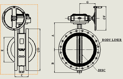
| DOUBLE FLANGE ( MODEL – 31 ) | ||||||||||
| SIZE | DIMENSION [mm] | |||||||||
| [in] | [mm] | A | B | C | D | E | T (MIN) | DIA F | G | VALVE ESTIMATED WEIGHT [Kg] |
| 3 | 80 | 128 | 81 | 114 | 190 | 0 | 24 | 250 | 212 | 12 |
| 4 | 100 | 146 | 95 | 127 | 230 | 0 | 24 | 250 | 212 | 16 |
| 6 | 150 | 174 | 132 | 140 | 280 | 57 | 26 | 250 | 212 | 23 |
| 8 | 200 | 198 | 179 | 152 | 345 | 132 | 29 | 350 | 240 | 37 |
| 10 | 250 | 244 | 232 | 165 | 405 | 190 | 31 | 350 | 240 | 54 |
| 12 | 300 | 275 | 257 | 178 | 485 | 244 | 33 | 425 | 226 | 80 |
| 14 | 350 | 371 | 282 | 190 | 535 | 276 | 36 | 600 | 320 | 105 |
| 16 | 400 | 390 | 315 | 216 | 595 | 316 | 37 | 450 | 312 | 146 |
| 18 | 450 | 425 | 347 | 222 | 635 | 368 | 40 | 600 | 312 | 173 |
| 20 | 500 | 451 | 382 | 229 | 700 | 421 | 43 | 600 | 337 | 206 |
| 24 | 600 | 510 | 460 | 267 | 815 | 511 | 48 | 600 | 337 | 323 |
| * AS STANDARD PRACTICE VALVES ARE SUPPLIED HAND LEVER UPTO 150 MM (6″) AND GEAR BOX ABOVE THAT SIZEGEAR BOX/ACTUATORS(ELECTRIC/PNEUMATIC) CAN BE SUPPLIED AS PER CUSTOMER’S SPECIFICATION FOR ALL SIZES | ||||||||||